The on-line instructions is long page designed
to be downloaded for continuous pages.
We are adding new pictures and when a new update to the product comes along it
is posted.
UPDATE February 10th
2002
You should be familiar
with the safety of running a aircraft with a propeller, and motor system. Keep your nose, ear lobes, toes,
tongue and fingers away from the propeller at all times.
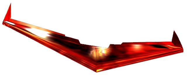
MEGA MANTA INSTRUCTIONS
The below detailed
instructions are for the beginning builder
Expert builders may have tricks of their own.
Ask
questions and send to:
mailto:dseth101@proseth.com
When building your MEGA MANTA you need to dry fit all components several times. Do not become impatient and start gluing things together until all servo wells, receiver and battery compartments are cut and the spline is fitted in place. You may need to sand the foam for smoothness and minor high spots.
PARTS
LIST FOR KIT 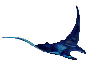
1. Two wing
halves,
right and left, cores and beds
2. One spline ( thin plastic wing joiner)
3. Two ailerons , tapered
4. Control horns
5. Control lines, w/clevis, w/control line housings
6. Adjustable cable connectors Rod Chuck
7. Wing tips (2 wing tips) (Balsa,)
8. ABS battery, motor, and speed control housing
9. ABS Cover Cowl
10. Balsa trailing edge and end caps
11. Velcro for motor keeper, and cowl retention
12. Hardwood spar for bowed spar
13. Hardwood cross member spar for HOT
SET UPS'
14. Aluminum motor mounting plate
with nylon hard point
THINGS YOU NEED FOR BUILDING ![]()
1. 3M #77 spray glue CAUTION
NEW FORMULA USE #78 IF IN CALIFORNIA
CAN BE FOUND AT WALMARTS ONLY!! Test the bed with any spray.
2. Putty knife and old butter knife
3. Heat source, flame from burner
4. Flat table top
5. GE silicon sealer
6. 50 grit & 100 grit sand Paper
7. Roll of Fiber packing tape 2, rolls of color covering tape or covering
material of your choice
THINGS YOU NEED TO FLY ![]()
1. Motor
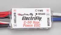
2. Speed Control
3. Battery pack
4. Battery charger
5. Prop
6. Gear box (and extra main gears)
7. Mixing 3 channel radio (FM)
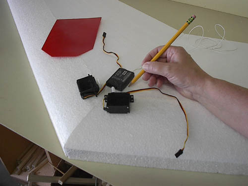
Before you dry fit the servos it is suggested you mock up the setup and
test for right, left, and center the servo throws
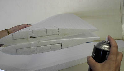
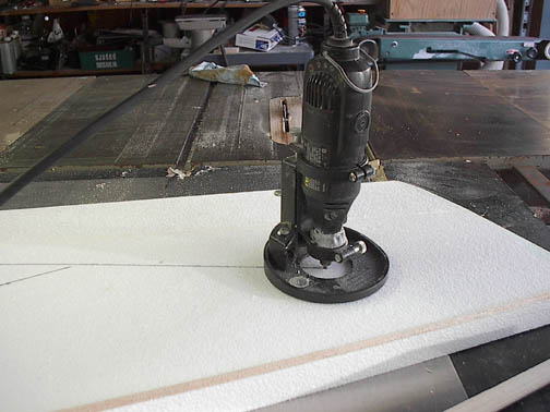
Your MegaManta is made of two kinds of foam, EPP, and white foam. Separate the top wing bed first and clean off EPP stringers.......with crisp plastic straight edge....credit card works too.
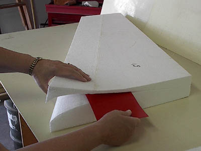
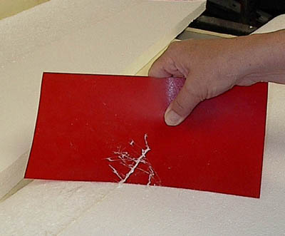
Use the spline (black or red) Use the spline to remove the EPP slag
PREPARING AND MAKING THE CAVITIES FOR THE ELECTRONICS
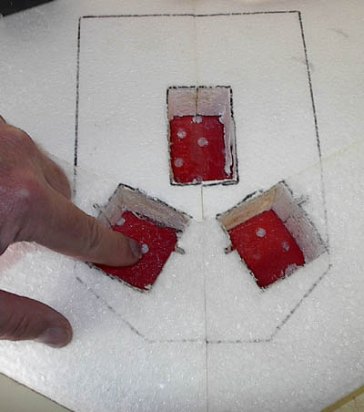
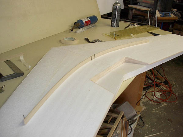
Lay out the positioning of the servos, battery and receivers from the top by marking the cores with a pencil. Outline should be as tight as possible without over lapping, see graphics below. Outline side profile. The bottom of the base line starts by placing the servo with the top of the servo arm just below the surface of the wing. Make a line then outline the battery, and receiver. For an electric version I recommend you cut the receiver from the top to the spline to provide access to the receiver through the motor and battery housing. Cut the spline to just fit the AIRBORNE package. Trim front corners back at the angle of the leading edge. For the electric version place the prop cut out template over the trailing edge and cut the spline accordingly. If you are going to put a hook you should make a hard point by placing 1/8 ply 1x1 on top and bottom of spline and screw the two pieces together.......glue will not work with the spline.
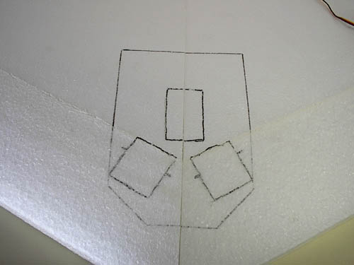
Bold dark
lines,
notice the servo notch is for a tight fit
Draw outline of servo's, receiver, and
spline Servo's arm determines the location of the
spline line
Draw the line to the block on sides to line up
your cuts
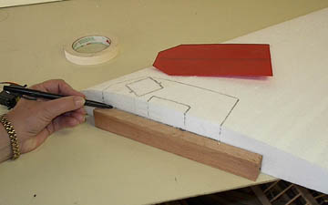
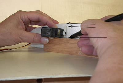
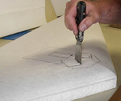
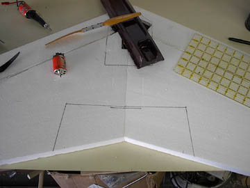
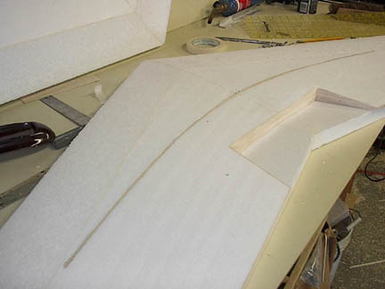
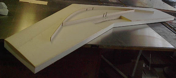
The graphics below shows a core
section, a block of wood, and a putty knife.
Notice the position of the servo. The servo's arm is just below the surface of the
wing core. This will give you the bottom line to place the block of wood to make
your first cut with a hot putty knife and side cuts with the butter knife. Caution!
Warning! Make sure the putty knife is not to hot and not to cool
but just right or you'll over size the pocket.
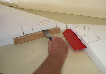
View above also shows the putty knife usage as
well
Use the bottom bed to keep parallel to the bench and wood block
The graphic above shows the slope version with receiver battery pack
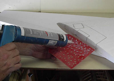
PREPARING THE SPLINE FOR GLUING
Drill 1/4" holes in
the plastic spline and sand the surface with 40 grit to provide a tooth for the GE silicon seal to make
the best contact. Use the GE silicon clear seal notice how I mentioned GE) on the
spline and
cavity in the foam that receives the spline. This will take 24 hours to set up.
To keep the two wing halves together during this drying time use 3M
#78 contacts
pray on the sides of the cores before applying the silicon seal to the spline. If
your dry fitting was good you will have a good joint. The joining of the sides
will be IMMEDIATE as the 3M #78 is set on contact and GE seal will set up in its
own time. 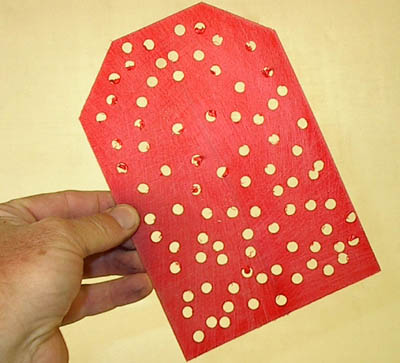
Make outline of battery pack and servo, just the out line. Dry fit the spline and slide both cores together and adjust the cut and cavities until all electronics, fit snugly.
Make an out line of the electronics on the spline and trim 40+or-Degres angels to match the leading edge, but back to battery's edge.
Dry fit first
Use the #78 3M spray glue on the
sides
Use the silicone seal on the spline
Make sure your dry fit is good. When wet joining be sure not
to let the sides touch until
the last moment and evenly.
CUTTING THE SERVO AND RECEIVER CUT OUTS
Once you have marked the top and sides you will see that if you remove the foam from the outlines you will have cavities to place the electronics . Make the putty knife long cut for the spline first, then the side cuts, then the top cuts. The servo holes should be cut just a little smaller than the servo except the area where the servo arm is located, and that needs to be slightly enlarged to allow free movement of the arm.
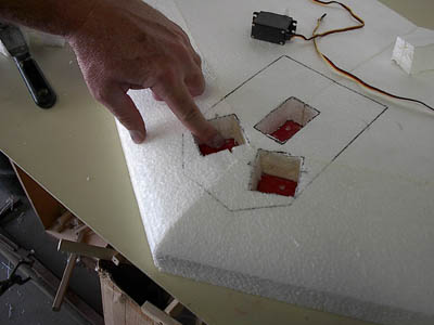
Cuts should be tight and down to the spline.
The electric version cut the receiver cavity from the top as well
I know you have been dry fitting all the foam, spline, servos, battery, lead nose weigh, wiring, switch, lunch box, right! Please say yes, dry fitting is the key to proper alignment, better to make the fit before you do it with glue.
CUTTING THE PROP CUT OUT
If you are making the electric mock up the motor and batter tray and draw a line parallel from the end of the tray. This line should be as long as the prop size plus 1/2 inch. Be sure this is 90 degrees to center seam. Next make 90 degree lines to the trailing edge. Make a mark 3/4 of inch toward the tip of each mark and you will have a tapered opening for the prop once you connect the marks. Use a razor saw and cut out the outline area at a 90 degree angle.
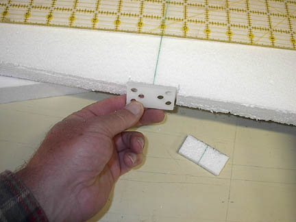
Use the small block of nylon included in the kit.
Make lighting holes or don't ---up to you.
Cut a notch for the block at the wing joint and glue in place before you glue the
balsa end cap on. This block will give you hard point to secure the motor plate to the wing.
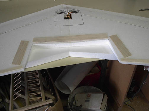
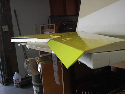
CAPPING THE TRAILING EDGES,
PROP CUT OUT, AND END CAPS
Glue by spraying the 3M #78 on the balsa and foam, trailing edges, balsa end caps, and wing tips. It is better to allow the balsa to over lap foam and trim by sanding until flush with foam. It is ok for the glue over spray to be on the top bottom and edges, it will be sprayed all over any way latter. Place some wax paper on the beds and use the beds to keep from bowing or arcing the trailing edges. There are two kinds of balsa tips; one is the tall vertical tips, two are the balsa end caps.
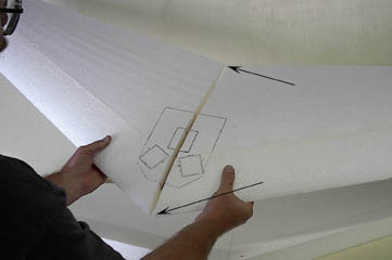
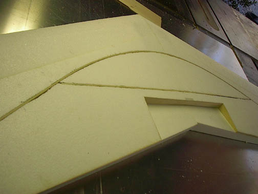
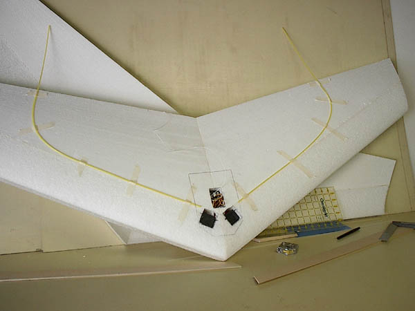
INSTALLING THE SPAR
The spar is designed to be loaded by pre bowing. First place the cores in the top bed with the bottom facing up. Make a mark approximately 10 inches from the nose crossing the seam of the two cores. Use 4 finishing nails small ones 1.5 inches long (thin). Insert two at the center marks and mark the center of the spar. Place the spar center behind the nails and bow the spar until the ends of the spar bow.
Mark the curvature of the spar and remove the nails and spar. Make a 1/8 wide
and depth of the spar notch with razor blade or drimel or fine tooth saw. Dry fit the spar and if
it is flush glue it in the slot. Next make a slot for the cross member spar (see
diagram below) as this additional spar support. To customize this spar for max
support cap the spar with 1/16 ply or balsa (not included in the kit)
The cross member is place just forward of propeller bay about 1inch
leave room for the finger well for hand launching.
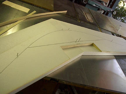
Draw with fine point marker the out line of the pre-positioned spars.
Remove the spars, nails, and route a slot for the spars to fit snuggly.
I use a drimel with a router attachment to cut the slot for depth and width.
Clean out slot and dry fit the spar and cross member spar. Once dry fit is flush
remove the spars and glue in place. Use thin ply or balsa as caps.
HOT SET UP USING CARBON FIBER
Epoxy resin and carbon fiber caps are recommended for hot
motor set up's. The carbon
fiber caps can be 3 oz carbon 1 inch wide and stippled with a brush until the
carbon is
saturated. Use a plastic squeegee to remove excess resin and if necessary blot
with paper towel.

Use the beds as molds by placing glad rap over the carbon and
align the top bed to the bottom.
Place with beds on a flat surface. Make sure the plastic rap is covering all
areas that the resin has touched...Place a long board to span the length and add
50 lbs of stuff on top to add pressure to the sandwich. Allow 12 hours for
resin to kick.
AILERONS
Dry fit the wing tips to end of the wings and use masking tape for a temporary
fit. Place the ailerons up to the tips and shape the ailerons to allow full movement
up and down adjacent to tips. For the electric version shorten the ailerons from
the center by distance of the prop cut out area.
Sand the ailerons and dry fit with masking tape and mark the location you decide
to place the control horns with a marker at the trailing edge and on the
ailerons. This should be the center of the length of the ailerons. Use CA to
create a hard point in 1 inch square around the area of horn placement.
Cover the ailerons first and make sure you wrote down the measurement of the
horn placement. Attach horns temporarily or do not tighten the screws
until after you have hinge taped them in place.
FITTING THE PUSH ROD HOUSING
FROM THE SERVO TO TRAILING EDGE
Use the push rod housings from the servo cavity as guide. Start at the
servo arm and use masking tape to temporarily hold the end of the push
rod housing so it is aligned to the servo arm. Bend the push rod housing so it aligns
at a 90 degree angle to the spot where you marked the control horn where it will be
positioned on
the ailerons. Tape
that end with masking tape. Adjust the push rod housing to make a tangent arch
from servo to the control horn location and every 4 inches tape to wing
surface. Push with your thumb like pushing on a thumb tack on push rod housing from the top until you make a continuous
depression the foam surface. This depression is the way to mark the channel you will make to fit
the push rod housing into. Do both sides. You not go all the way to the
trailing edge but two inches from it to allow the angle of the push cable to align
with the control horn.
Take off the temporary tape and cut with drimel or make a sanding fixture to
form a channel just deep and wide enough to inlay the push rod housing.
The tighter the fit the better. Cut the push rod housing back at each end to
allow the push cable and clevis to clear for maximum throws. Dry fit do not
glue yet!
ANTENNA HOUSING PLACEMENT
The antenna needs to go some place so cut a slightly deeper channel just like the one you made for the push rod housing on the top of one of the wings to allow a antenna housing tube to go from servo cavity to wing tip. You will feed the antenna from receiver cavity route through servo cavity to the inlayed antenna housing. The antenna housing channel will on the EPP and White foam seam. You are dry fitting still. The antenna housing channel will be under the control cable channel so from the point to where the control cable housing curves toward the control horn the channel will be deeper by the depth of the housing. When you use the 3 M contact glue #78 to glue in the housings you need to be careful not to get any glue inside the housings. Be sure to protect the ends with a removable plug of wax, wax paper, ect. No gluing yet!
PREPARING THE CABLE, AND
CLEVIS
Flux the ends of both cables,
flux the interior of the clevis, place a length of solder in side the clevis,
tin the end of cable to be soldered to the clevis. Us a heavy iron or a flam
from a burner to reach full flow head of the solder. Attach the cable adjusting hardware
to the horns. For more throw in the top hole, less in bottom hole of the horn.
CHECKING THE FIT AND PLACEMENT
OF THE COMPONENTS
Place the servos in the servo
cavities. The servo arms should be facing the front and line up with the control
line housing channel. Spray silicon lube into the antenna housing to provide lubrication
to slide the antenna through when the time comes. Place the antenna housing in
its channel (dry). The end of the channel should be tapered downward to keep
clear from servo arms throws. This is done with the hot knife or careful
sanding.
With masking tape, tape the ailerons to the trailing edge. The horn should be in
line with the control cable housing. (this is a temporary tape job)
Dry fit the control line housing into the groove and allow for clevis clearances
and full servo arm throws. This housing will extend about 1 inch from
where the aileron horn will be when it is attached. This should allow the
cable when inserted to flow into the adjusting hardware on the horn. Test the
cable (after silicon lubing) bare end through the housing from the servo end so
it will go to the horn and run it through the adjusting hardware. You
should have cable sticking out past the horn which you will adjust it's length
later.
ONCE you are satisfied with fit and the clearances of servo arm throw, and
length of the housing cap the ends of the housings ( remove the cables)
and with your choice of plugs to keep any glue from getting in side the housings
glue them in place using the marks you made to remember where they fit best.
Remove the masking tape and ailerons and tips if they are still temporarily
taped on. Spray the 3M #78 glue in the grooves and on the housings. Push them in
place while the glue is still somewhat wet to allow the ease of insertion. The
housings should be flush with surface except the last inch or so of the cable
housing closest to the horn. It is not recommended to fill the slight amount of
void just above the housings as tape will cover it nicely.
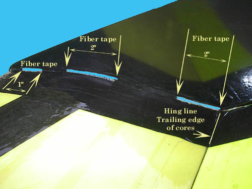
TAPPING THE LEADING EDGE, TRAILING EDGE, CROSS TAPPING AND CENTER SECTION

Use the beds to maintain the proper shape of the wing. If you distort the wing by pulling the tape to tight it will not fly as well......
Reinforced fiber tape 2 inch wide
is used to provide your Mega Manta with super structure reinforcement.
The
3M #78
glue is imperative to be used to allow the tape to adhere to as the
sticky tape is not enough by its self. Before you use the glue and tape
this, is the time to do the final sanding of the
surfaces with light sand paper. Your leading edge should have been sanded
to the final shape with courser sand paper.
Cover any openings of the receiver and servos by wading up news paper.
The news paper should be flush with surface. You will need to do sections at a
time. Spray the center section 4 inches to the right and left of the
center of the wing top first. Allow the spray glue to become tacky then at
90 degrees place two, three and eight inch lengths of tape from nose to trailing
edge. Do the bottom the same.
Next do the trailing edge, one piece full length of the one wing section. Allow
the spray to dry to tacky. Pull the tape taunt and place the tape so the center
of tape provides the top and bottom of the tape to over lap the top and bottom
of the wings trailing edge. If you pull the tape to tight you will cause a warp
in the trailing edge do not do this as the ailerons will not fit properly when
you tape them on.
Do the leading edge the same however over lap three lengths of tape to each wing
section.
Be sure to spray the glue where the tape is going to be and dry to tacky.
NEXT cross the tape from the wing tip's leading edge to trailing edge to
center section. The long crossing tape each wing panel top and bottom.
Pull the tape taunt and do not over stretch the tape as to distort the
wing. This not easy so use the beds as your guide.
Now that the fiber reinforced tape is in place allow it to dry. You will find some hanging from the tips or in other places trim these area as you go.
COLOR TAPE THE MEGA MANTA
 http://www.tgworks.com/colored_packing_tape.htm
When taping with the color tape do a panel section at a time over lapping and crossing is advised. You must use 3M#78 spray glue to tacky before you put any tape on.
It's wise to make the top a different color than the bottom to see what side is up when you are at speck. Yellow bottom ailerons and black bottom wing is the best combination for visual contact at speck. The center section can have over lapping colors from the nose to the trailing edge to cover the center section over laps. It's your Mega Manta do what ever color combinations you want. An option is using same coating as other planes but remember the hot blow dryer or iron will cause the foam to melt. Do not expect the tape job to look like a covering over fine sanded balsa. It's foam and strapping tape and you will see the bumps and wrinkles. If you want the smooth high tech finish with foam. " it won't happen". Smooth yes, but not perfect. Don't use contact paper unless you want to pay the price of weight. Every ounce you save is more stick time.
Look for new step by step digital pictures to be added to the
instructions
Way to much detail but the first time builder will love it....."O
Yeah!"
Each step is in picture form
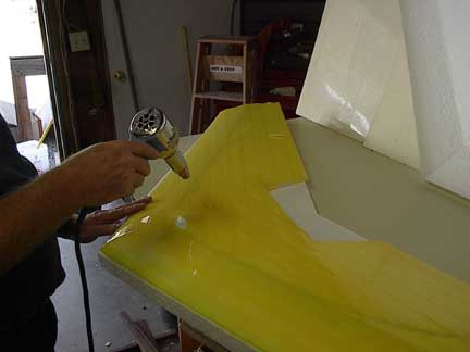
The color tape can be tricky to use as wrinkles will be inevitable. With a good deal of caution and some practice on the beds. you can use a heat gun to smooth out the wrinkles and tighten the tape job to good surface finish. CAUTION! To much heat can cause warps, melts, and dull spots...........practice first.
TAPE HINGES FOR THE AILERONS
Use 2 inch wide packing tape or the colored tape and tape the top edge of the aileron to the top edge of the trailing edge. The aileron should be facing down as not to create a ripple in the hinge. You can position aileron with scotch tape to insure a clean full length contact of the two side edges. Once you have taped the top hinge fold the aileron completely over until it is flush with top of wing. Do not let wide gaps to spread the two edges. Press down with fingers and tape the ends and middle with small lengths of scotch tape. Use the 2 inch wide tape of your choice and tape the bottom of the aileron with over lapping tape press out as not to create air pockets or wrinkles. Replace the horns in the same holes you made with test fitting.
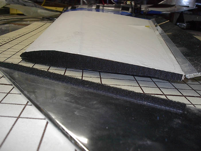
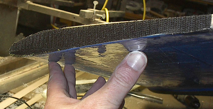
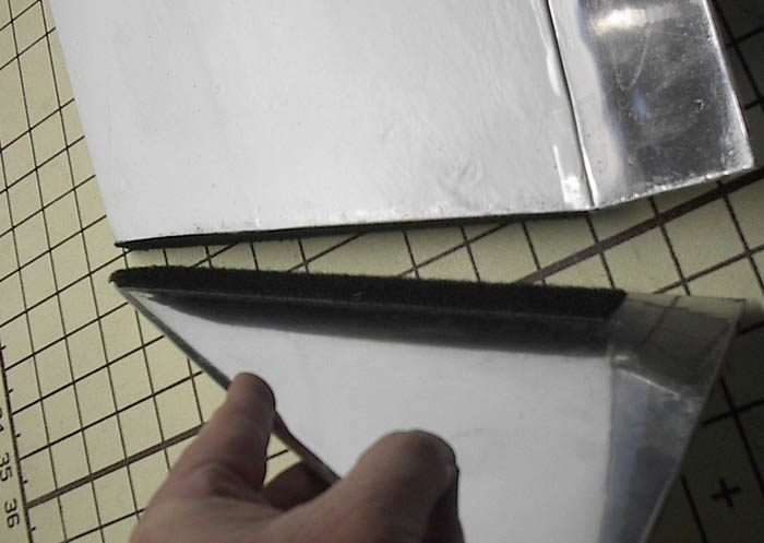
BALSA TIPS & VELCRO
The balsa tips are cut 90% of way. You need to round over the leading edge and cut 1 inch lighting holes if you want to make them lighter. After sanding to thickness and round over you like, I run CA on all edges to provide extra strength and reducing warp. Sand with 320 or 400 grid for additional smoothness. Cover with the iron on covering of your choice and attach the wing tips with Velcro. Yes Velcro I was surprised to find Velcro works well and with many loops, and rolls no loss of tips...yet.
ATTACHING THE ABS WING TIPS (OPTIONAL)
ABS tips will flutter at
dive speeds with standard set up. With higher
speeds of the hotter set up tip flutter is expected at flat out speeds.
The balsa tips are recommended unless you are using the Mega Manta
as a slope combat ship. The ABS tips are now special order.
You can use the 3M#78
spray glue on the section that will be
against the balsa end caps. If you have high power 3M 90 spray glue do not use
on foam but this glue will bond the ABS to the balsa tips. For extra
security the tips should be slotted for fiber tape. The tips should be slotted
just above the top wing surface to allow fiber strapping tape to be inserted and
wrapped around from top through the slots and finish wrapped on the
bottom. The tape short lengths should be 3 inches long. Two slots
should be cut 1/16 of inch by 2 inches.

Cut 2 inch slots, 1/16 high level with top. 1 inch slot
optional, Last slot should be parallel with the trailing edge of the cores at
the aileron hinge line to prevent tip flutter.
Tape over fiber tape for trim.
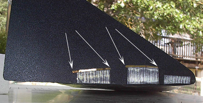
Run fiber tape through holes and wrap around wing top and bottom.
Slot to rear should be opposite the cores trailing edge to prevent tip flutter.
TRAP DOORS FOR SERVO AND RECEIVER ACCESS
Locate the opening over the servos
and receiver by feel and cut an opening and make a door by tapping tape to its
self and use the tape hinge method for access doors. You may
need the space just above the servo for balance weight to be placed. This
locations is suggested as you have access to ad or remove weights. Weights need
to taped in with double face carpet tape. Your on off switch can located with the
cavity as well.
INSTALLATION OF RADIO AND SET UP
Replace the horns and the
adjusting hardware. Run the cables through the control housings ( only after you
removed the safety glue plugs) feed into the adjusting hard ware.
Let the cables be long for now. Clip the clevises to the servo arms and test the
radio gear and throws. Use an receiver pack if you are building the electric
version first to check out the system.
Start the CG at 10 5/8 inches from the nose.
The ailerons should be in neutral when the trailing edges of the ailerons are in a reflex position at a 8 to 12 degree angle. This angle may vary with CG and sweet spotting your Mega Manta. Start the CG at 10 5/8 inches from the nose. The suggested CG is just that SUGGESTED. Experts may want it back more and if your starting out, nose heavy is a good place to start. The electric version is very close to CG when using suggested power packs and by placing the AIRBORNE batteries forward or back you can find the spot that is best for your flying style.
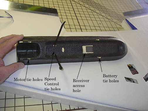
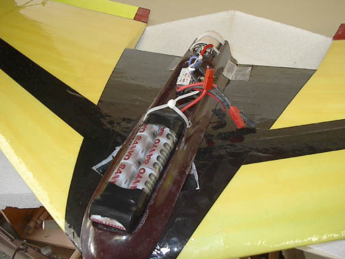
ELECTRIC BATTERY PACK AND POD
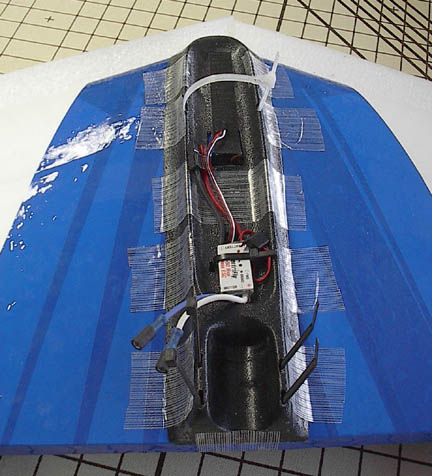
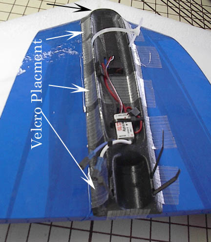
Use 3M 90 contact spray on the sides of the battery saddle to provide a stickier
surface for
the fiber tape. You can cover the tape with same color tape to hid its over
flow. See picture on the right. Also use 3M 90 on the tape for the Velcro
placement to hold down the
cowl cover.
You will be cutting holes in the battery and motor saddle for receiver access, speed control
access, and motor mounting.
Use tie downs for holding in all components and Velcro for holding down the
battery pack and Pod. You should also use a couple of loose tie downs for
the power pack as well as the Velcro. Loose enough to slip in a newly charged
battery pack over the Velcro.
ELECTRIC MOTOR SET UP
When placing
the motor in its curved bay you may need to remove some of the ABS to allow
the brushes to move freely and allow room for the lead wires. To mount the
motor use the aluminum motor mount included in the kit. Use a Velcro tie strap
or a release tie strap to hold down the motor. When the gear box and
motor are joined place the aluminum motor mount in-between them. The mount will
extend below the motor tray and the two holes are now ready to receive two hold
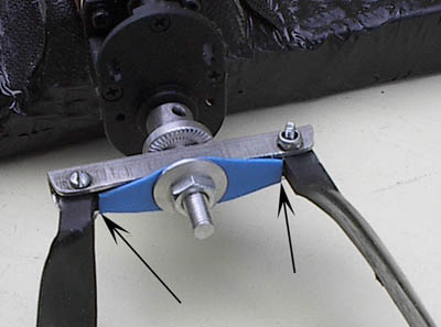
down screws. The pictures below show a PC board and the PC board has be up
graded to aluminum for its heat sink quality's. An aluminum mount can also
bend to provide a more precise motor thrust angle. The nylon hard point that you
installed earlier is was the motor mount screws, screw into. Drill a small
pilot hole and use a self tapping screw. This set up allows you to exchange
motors in two minutes or less.
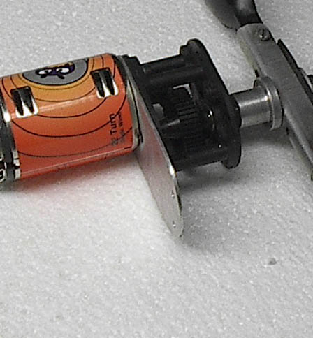
The plate is set in-between the gear box and the motor and
will extend below motor tray and screwed to the imbedded nylon
hard point. The new mount is aluminum.
Motor Incident
The motor incidence angle is set to neutral. However
some like 1 or 2 degrees of positive or negative bend or shim the aluminum
mount to make the adjustment. Place the motor, and
electronics on to the battery motor saddle and center the works nose to nose without the
prop. Place the Mega Manta on the
bottom beds and align and tape the saddle in place. Set the whole works on a table
top and fit a brass tub the size that will fit over the motor shaft and at least
12 inches long. This will extend the motor shaft beyond the foam parallel
to the table surface to check the incident angle. We suggest 0,0 degrees, however you may
have preferences of + or -.
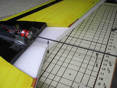
Use a brass or fiber tubing the size of the motor shaft to see the thrust lines.
With the wing in the beds place the tubing over the shaft as the ID of the
tubing should be the same as the OD of the motor shaft. The angle of the tubing
will show positive or negative motor thrust incident.
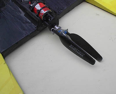
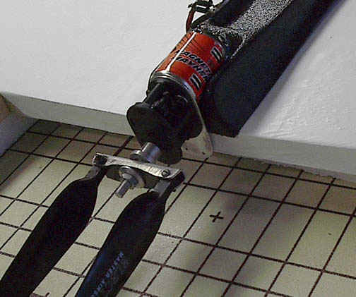
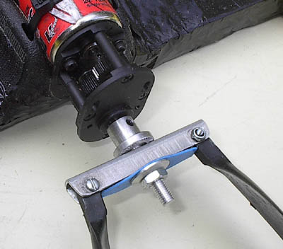
Take off the prop spinners there not needed Turn the prop
around from the puller to a pusher
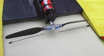
Extended prop when power is on See the prop keeper- this keeps the prop from folding back to far and jamming together. UP DATE- An aluminum keeper is now included in the kit.
THE LAST THING TO DO IS A SAFETY THING FOR LAUNCHING.
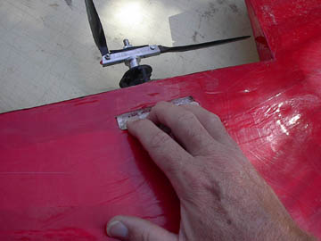
CUT A 1/2 INCH SLOT 2 INCHES LONG JUST BEHIND THE MOTOR ON THE BOTTOM AND CENTERED BETWEEN THE TWO WING HALVES. MAKE IT 1/2 INCH DEEP AND YOU HAVE A FINGER SLOT FOR LAUNCHING. THE PICTURE ABOVE SHOWS THE WHITE FOAM. LINE THE INSIDE WITH TAPE FOR A SMOOTH LOOKING HOLE.
WHEN YOU LAUNCH THE WING WITH THE FINGER HOLES BE SURE TO COUNT TO 3 BEFORE YOU HIT THE THROTTLE. SAFETY IS PARAMOUNT WHEN A PROP IS SPINNING AT 8,000 RPM YOU DO NOT WANT YOUR FINGERS IN THE WAY!!!!. IF YOU CAN NOT LAUNCH WITH A THROW THEN INSTALL A HOOK AND LAUNCH WITH A HIGH START.
Basic power and drive options
1
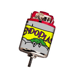 16x2 Motor Kyosho EndoPlasma LXW933
http://www2.towerhobbies.com/cgi-bin/wti0001p.pgm?Q=1&I=LXW933&P=7
 http://www2.towerhobbies.com/cgi-bin/wti0001p.pgm?Q=1&I=LXSL79&P=M
2.
Great Planes 3.8:1pinion gear GD-600 gear box
with Kyosho EndoPlasma 8 cells
http://www2.towerhobbies.com/cgi-bin/wti0001p.pgm?Q=1&I=LXTG41&P=M
Special order 10 tooth pinion gear& GD-600
gear box with Endo Plasma 9 cell
http://www.newcreations-rc.com/
Brushless Option
A great way to fly is brushless!
In the long run more economical by far.
The Mega Motor Acn22/30/3 & Phoenix 45amp speed control with more options.
12/6.5prop.
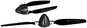
4. Master Air Screw 12/8 folding prop http://www2.towerhobbies.com/cgi-bin/wti0001p.pgm?Q=1&I=LXZ997&P=7

Now available the Mega Manta 8 "subC" Yellow Jacket Battery Pack.
Sanyo yellow jacket battery 2400mAh pack $55.00 with
your order of a Mega Manta.
5. 2400mah "sub C" - 8 to 10 cell with proper pinion
gear.

Packing tape is available from your local Hobby store or look in yellow pages for packing supplies. We do not include the tapes as they are an extra expense, to you, to ship.
FLY IN A OPEN AREA AND AWAY FROM BUILDINGS AND PEOPLE- SAFETY PRACTICES AND AMA RULES SHOULD BE FOLLOWED AT ALL TIMES. DO NOT HIT THE THROTTLE UNTIL YOU HAVE LAUNCHED YOUR AIRCRAFT....FLY AND OPERATE AT YOUR OWN RISK. THIS AIRCRAFT IS NOT FOR BEGINNERS!